In a nominal T model of a medium transmission line, the series impedance is divided into two equal parts, while the shunt admittan...
In a nominal T model of a medium transmission line, the series impedance is divided into two equal parts, while the shunt admittance is concentrated at the center of the line.
Here,
Series impedance of the line Z = R + jX
Shunt admittance of the line Y = jwc
Receiving end voltage = Vr
Receiving end current = Ir
Current in the capacitor = Iab
Sending end voltage = Vs
Sending end current = Is
Sending end voltage and current can be obtained by application of KVL and KCL. to the circuit shown below
Current in the capacitor can be given as,
By Kirchoff’s current law at node a,
or
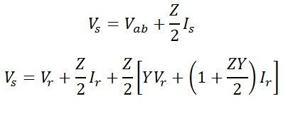
By Kirchoff’s voltage law
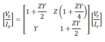
Equation of Sending end voltage Vs and current Is can be written in the matrix form as

Also,
Hence, the ABCD constant of the nominal T-circuit model of a medium line are
The phasor diagram of the nominal T-circuit is shown below. It is drawn for a lagging power factor.
In the phasor diagram:
OA = Vr – receiving end voltage to neutral. It is taken as a reference phasor.
OB = Ir – load current lagging behind Vr by an angle ∅. cos∅ is the power factor of the load.
AC = IrR/2 – Voltage drop in the reactance of the right-hand half of the line.It is perpendicular to OB, i.e., Ir.
OD1 = Vab – voltage at the midpoint of the line across the capacitance C.
BE = Iab – current in the capacitor. It leads the voltage Vab by 90.
OE = Is -sending-end current, the phasor sum of load current and capacitor current.
D1C1 = IsR/2 – voltage drop in the resistance on the left-hand side of the lines.It is perpendicular to Is.
C1D = Is X/2 – voltage drop in the reactance in the left half of the line. It is perpendicular to Is
OD = Vs – sending end voltage. It is the phasor sum of the of Vab and the impedance voltage drop in the left-hand half of the line.
∅s – phase angle at the sending end. cos∅s is the power factor at the sending end of the line.


COMMENTS